Introduction
This document elucidates the principal factors influencing thermal exchange between the refrigerant and the airstream within a plate finned-tube heat exchanger, commonly referred to as an evaporator or condenser coil in air conditioning (AC) systems. The primary considerations explored encompass the internal heat transfer coefficient, the thermal contact resistance manifested between the fin and the tube, and the external heat transfer coefficient. Empirical correlations are delineated to facilitate the quantification of heat transfer rates associated with each of these factors. Furthermore, supplementary design aspects pertinent to these three thermal transfer mechanisms are presented and deliberated upon. The discussion extends to encompass in-tube augmentation, the ramifications of oil-refrigerant mixtures, and the phenomenon of frosting, given their consequential impact on heat transfer within the coil. Additionally, methodologies for tube circuit configuration and the prevailing standards for coil performance rating are outlined.
1. Thermodynamic Cycle in Air Conditioning Systems
1.1. Vapor-Compression Cycle Fundamentals
A representative vapor-compression cycle inherent to air conditioning systems is illustrated in Figure 1. The fundamental constituents depicted in this schematic are ubiquitous across various system configurations. Notably, the expansion valve and accumulator represent relatively uncomplicated and cost-effective components. Consequently, the evaporator and condenser, in conjunction with the compressor, constitute the primary elements of the system in terms of capital expenditure, spatial footprint, and the potential to influence operational expenses—specifically, compressor power consumption—via judicious design choices.
1.2. Pressure-Enthalpy Diagram Analysis
Figure 1 additionally features a pressure-enthalpy diagram delineating both idealized and actual vapor-compression cycles. The numerical annotations on this diagram denote the thermodynamic state of the refrigerant as it traverses the evaporator and condenser. In particular, a saturated mixture ingresses the evaporator (point 4), and superheated vapor egresses (point 1a). Conversely, for the condenser, superheated vapor enters (point 2a), and subcooled liquid exits (point 3).
1.3. Operational Pressure and Temperature Regimes
Furthermore, Figure 1 underscores the differential pressure and temperature regimes characterizing condenser and evaporator operation. Condensers function under elevated pressures and temperatures, whereas evaporators operate at comparatively diminished pressures and temperatures.
2. Air-to-Refrigerant Heat Exchanger Configuration
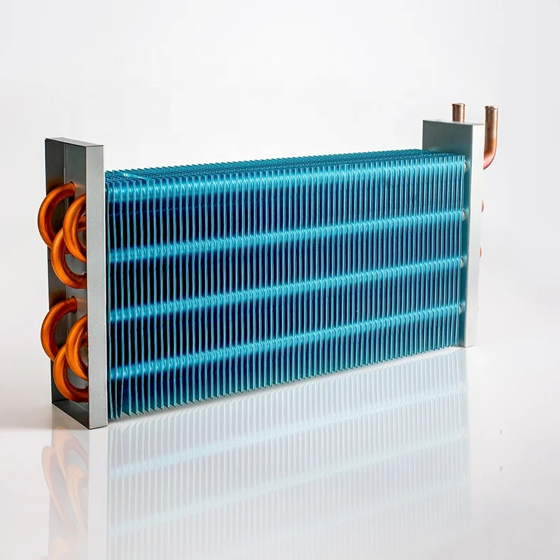
2.1. Plate Finned-Tube Heat Exchanger Architecture
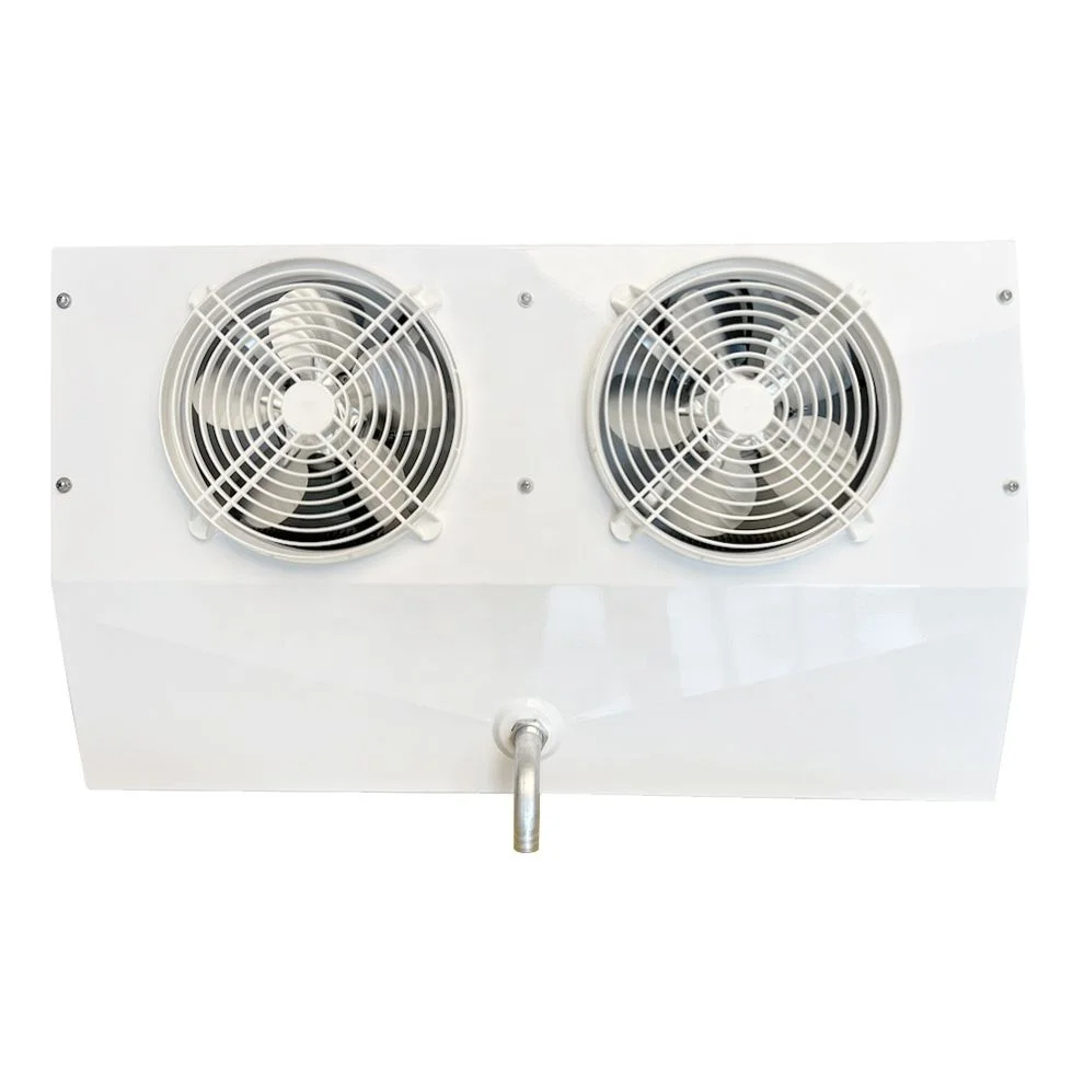
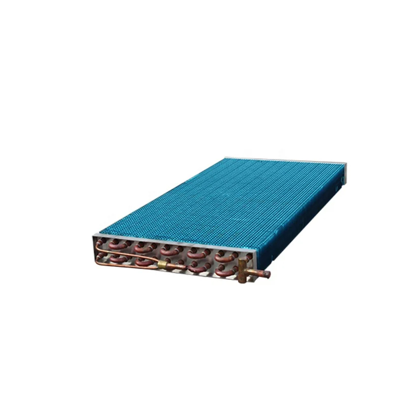
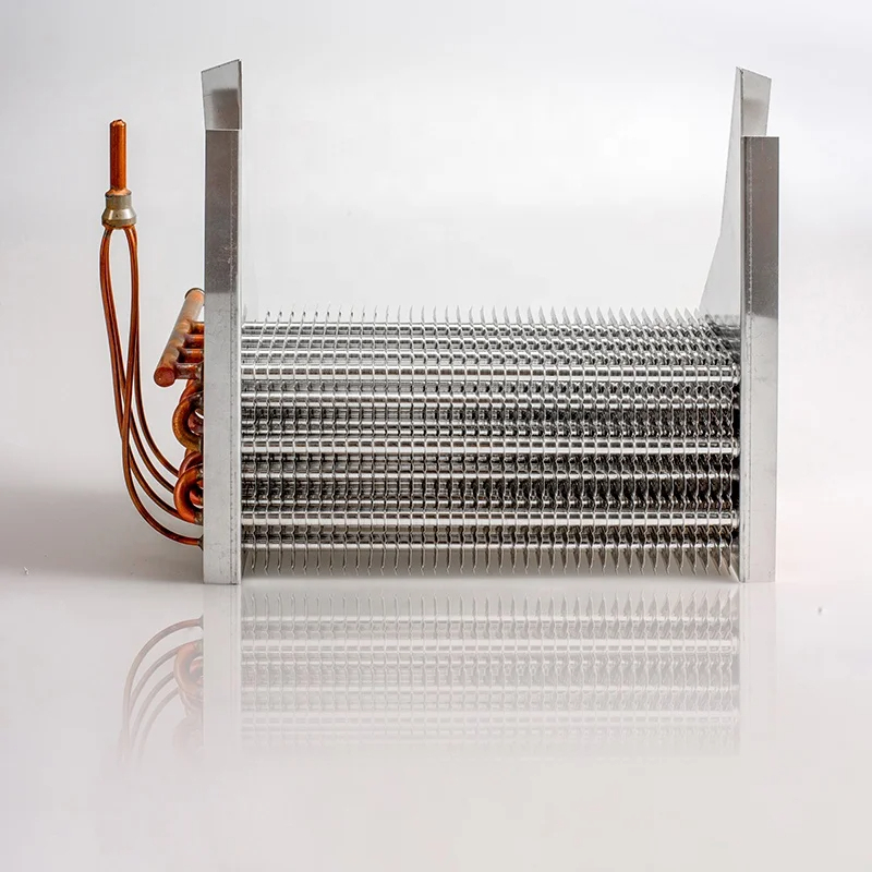
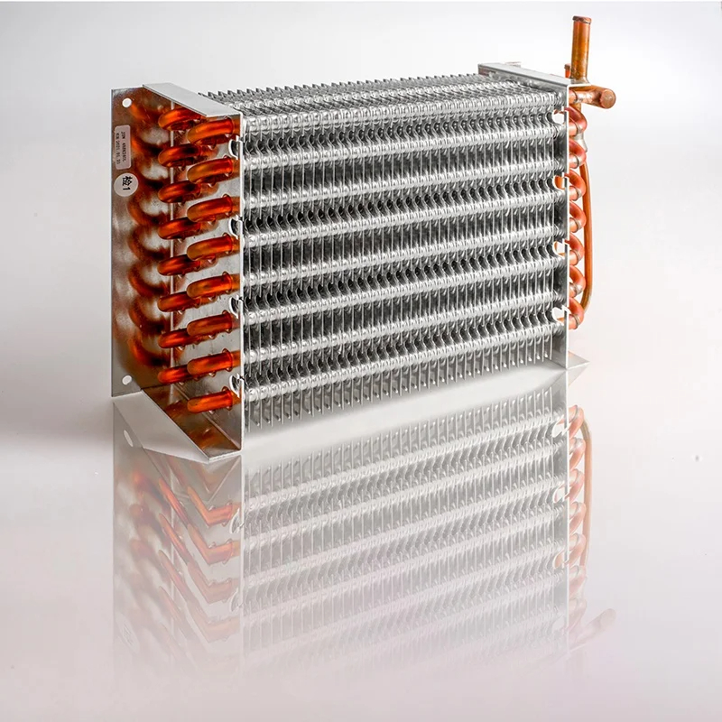
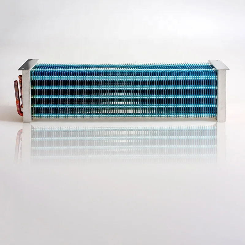
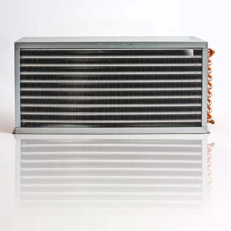
The prevalent configuration for air conditioning evaporators and condensers is the air-to-refrigerant heat exchanger typology. Predominantly, airflow is directed across a circular tube bank augmented with continuous plate fins, as depicted in Figure 2. This structural arrangement lends the nomenclature “plate finned-tube heat exchanger.” The evaporating or condensing refrigerant circulates through tubes oriented perpendicularly to the airflow, arrayed in staggered rows.
2.2. Coil Circuitry and Material Composition
The end views presented in Figure 2 reveal the interconnectivity of the tubes, enabling their coiling to achieve diverse configurations of passes, rows, and parallel flow paths. This characteristic justifies the appellation “evaporator and condenser coil.” Typically, the fins are fabricated from aluminum, while the tubes are constructed from copper. However, instances exist where both constituents are manufactured from a homogeneous material. The fins are affixed to the tubes by inserting the tubes into apertures stamped into the fins and subsequently expanding the tubes via mechanical or hydraulic processes.
3. Challenges in Evaporator and Condenser Coil Design
3.1. Limitations of Classical Heat Exchanger Analysis
The design of evaporator and condenser coils is fraught with complexities, a principal one being their inapplicability to conventional heat exchanger analysis methodologies, such as the Logarithmic Mean Temperature Difference (LMTD) and effectiveness-Number of Transfer Units (NTU) methods. This limitation stems from the refrigerant’s potential to exist in either a single-phase or two-phase state across substantial portions of the heat exchanger length. Such phase transitions engender variability in specific heats and convective heat transfer coefficients for the refrigerant.
3.2. Complications of Two-Phase Flow and Uneven Thermal Loading
Furthermore, analyzing each phase region independently is complicated by the intricate tube circuitry and the non-uniform heating or cooling of the airstream. Consequently, a precise analysis or design of a coil is most effectively accomplished by conducting energy balances on discrete, short segments of tubing.
4. Energy Balance Approach for Coil Analysis
4.1. Application of Overall Heat Transfer Coefficient
If the tube segment length is judiciously chosen such that variations in fluid properties and convective heat transfer coefficients are minimized, an overall heat transfer coefficient can be employed for the energy calculations. This coefficient can be articulated in terms of thermal resistances, adhering to the methodology expounded in established heat transfer literature.
4.2. Major Factors Affecting Thermal Resistance
In the context of evaporator and condenser coils, the predominant factors influencing the aggregate thermal resistance are the refrigerant-side and air-side convection coefficients and the thermal contact resistance arising between the fin and the tube.
5. Refrigerant-Side Heat Transfer Coefficient
5.1. Factors Influencing In-Tube Convection
The refrigerant-side heat transfer coefficient is significantly influenced by the flow regime within the tubes, which can be either single-phase (liquid or vapor) or two-phase (a mixture of liquid and vapor). In the case of single-phase flow, established correlations for turbulent flow in tubes can be employed.
5.2. Considerations for Two-Phase Flow
For two-phase flow, the heat transfer coefficient is a function of the refrigerant’s quality (mass fraction of vapor), the mass flux, and the tube’s geometry. The complex nature of two-phase flow necessitates the use of specialized correlations, often derived empirically, to accurately predict the heat transfer coefficient. These calculations are important in hvac systems.
5.3. Impact of In-Tube Augmentation
In-tube augmentation techniques, such as the use of micro-fins or twisted tapes, can enhance the refrigerant-side heat transfer coefficient by increasing turbulence and promoting better mixing of the two-phase flow.
The thermal contact resistance between the fin and the tube is a critical factor affecting the overall thermal performance of the coil. This resistance arises due to the imperfect mechanical contact between the fin and the tube, which creates microscopic air gaps that impede heat transfer.
6.2. Influence of Manufacturing Processes
The magnitude of the contact resistance is strongly influenced by the manufacturing processes employed to assemble the coil. Factors such as the expansion method (mechanical or hydraulic), the expansion force, and the surface finish of the fin and tube can significantly impact the contact resistance.
6.3. Minimization Strategies
Minimizing contact resistance is crucial for optimizing coil performance. Techniques such as using a tight fit between the fin and tube, applying a thermal grease or coating, and employing advanced bonding methods can help reduce this resistance.
7. Air-Side Heat Transfer Coefficient
7.1. Dependence on Airflow Characteristics
The air-side heat transfer coefficient is primarily dependent on the airflow characteristics, including the air velocity, the fin geometry, and the spacing between the fins and tubes.
7.2. Influence of Fin Geometry
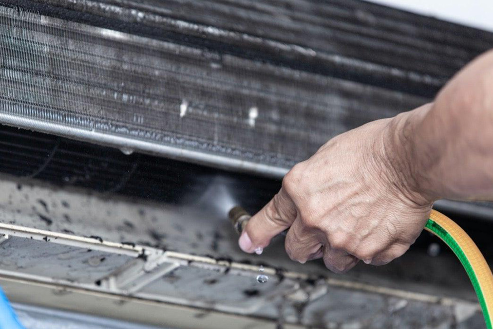
The fin geometry plays a crucial role in determining the air-side heat transfer coefficient. Factors such as fin density, fin thickness, and fin shape (e.g., plain, wavy, louvered) significantly influence the airflow pattern and the resulting heat transfer. It’s important to clean fins to maintain optimal efficiency. Coil cleaning is essential in hvac systems.
7.3. Optimization of Fin Design
Optimizing the fin design involves balancing the need for a high heat transfer area with the requirement to minimize pressure drop across the coil. Advanced fin designs, such as louvered or offset strip fins, can enhance heat transfer while maintaining acceptable pressure drop levels.
8. Additional Design Considerations
8.1. Effects of Oil-Refrigerant Mixture
The presence of lubricating oil in the refrigerant can significantly affect the heat transfer performance of the coil. Oil can increase the viscosity of the refrigerant, leading to a reduction in the heat transfer coefficient, particularly in two-phase flow.
8.2. Impact of Frosting
Frost formation on the evaporator coil surface can severely degrade heat transfer performance by adding an additional thermal resistance and reducing airflow. Defrost cycles are often employed to mitigate the effects of frosting, but they can also reduce the overall efficiency of the system.
8.3. Tube Circuiting Procedures
The arrangement of tubes within the coil, known as tube circuiting, plays a vital role in determining the overall performance of the coil. Proper circuiting ensures uniform refrigerant distribution and optimal utilization of the heat transfer surface. Factors to consider are the evaporator and condenser coils.
9.1. AHRI Standard 410
The Air-Conditioning, Heating, and Refrigeration Institute (AHRI) Standard 410, “Forced-Circulation Air-Cooling and Air-Heating Coils,” provides a standardized method for rating the performance of evaporator and condenser coils.
9.2. Eurovent Certification Programs
Eurovent Certification offers various certification programs for air conditioning products, including evaporator and condenser coils. These programs provide independent verification of product performance and energy efficiency.
10. Emerging Trends in Coil Design
10.1. Microchannel Heat Exchangers
Microchannel heat exchangers, characterized by their small hydraulic diameter channels, are gaining increasing attention as a promising alternative to traditional finned-tube heat exchangers. They offer advantages such as higher heat transfer coefficients, reduced refrigerant charge, and improved compactness.
10.2. Nanofluids and Enhanced Surfaces
The use of nanofluids, which are suspensions of nanoparticles in a base fluid, and enhanced surfaces, such as micro-structured or coated surfaces, are being explored as potential means to further enhance heat transfer in evaporator and condenser coils. HVAC engineers always try to improve heat transfer.
10.3. Additive Manufacturing
Additive manufacturing, also known as 3D printing, is emerging as a potential fabrication method for producing complex and customized coil geometries that can optimize heat transfer and reduce pressure drop.
Key Takeaways:
- The design of AC evaporator and condenser coils is a complex process involving multiple interacting factors.
- The refrigerant-side heat transfer coefficient, thermal contact resistance, and air-side heat transfer coefficient are the primary factors influencing coil performance.
- Classical heat exchanger analysis methods are not directly applicable to evaporator and condenser coils due to the presence of two-phase refrigerant flow.
- An energy balance approach on short tube lengths is recommended for accurate coil analysis.
- In-tube augmentation, oil-refrigerant mixture effects, and frosting can significantly impact heat transfer.
- Proper tube circuiting is essential for uniform refrigerant distribution and optimal coil performance.
- AHRI Standard 410 and Eurovent certification programs provide standardized methods for rating coil performance.
- Microchannel heat exchangers, nanofluids, enhanced surfaces, and additive manufacturing represent emerging trends in coil design.
- Careful consideration of these factors during the design process can lead to significant improvements in the efficiency and performance of air conditioning systems.
- Optimization of ac coils is vital for system efficiency.